Few boating experiences are more frustrating than preparing to go for a cruise and finding that your battery doesn’t have the power to start the engine. In today’s boats, there are a lot of parasitic loads—minute electrical loads inherent to the vessel such as stereo memory, carbon monoxide detectors and LED indicator lights— built into a variety of pieces of marine hardware. Add in bilge pumps and pump switches, engine control modules and alarm systems, and it pulls down your battery voltage over time. Even without parasitic loads, batteries will slowly discharge. A common lead-acid wet-cell battery will discharge about five percent a month. Left unattended, unchecked and uncharged, these battery drains will drop the battery voltage below what is required to turn over the engine. Adding a battery charger is the obvious solution, and it’s a good winter project.
Selecting a charger
It might be tempting to buy an inexpensive automobile charger, but that’s not a good idea. They cost less, but they are inappropriate and even dangerous for a permanent marine installation. The battery charger is one of the few boat components that connects to the boat’s shore power alternating-current (AC) system, supplied from shore power, and the boats direct-current (DC) battery system. As such, a careful and proper installation is essential to ensure safety.
The selection of the best battery charger for your boat is first a function the size of your battery bank measured in amp hours, the chemistry of your batteries, and the duty cycle of the boat. These are the most important factors in selecting a charger. It’s a subject worthy of a separate article.
The charger’s maximum output should be approximately 20 to 40 percent of the battery’s storage capacity, often rated in cold cranking amps (CCA). The battery charger output must match the requirements of the battery chemistry. Gel batteries have different charge rates and charge profile than wet cell batteries. Fortunately, most marine battery chargers have options to suit each battery chemistry and are programmed as three-stage “smart” chargers. For maximum battery life, the charger has a bulk charge phase, which will replace the charge up to 80 percent of capacity. The charger will then shift into the absorption phase where the final 20 percent is replaced at a constant voltage and declining amperage. The final stage is the float stage, which maintains the battery at full charge.
Gas vs Diesel Fuel System
Federal law requires that electrical devices in the engine space and connected compartments of a boat powered by inboard gasoline engine must be ignition protected. This means that in its normal operation, the device must not be able to ignite a specified mixture of explosive gas. Many automotive chargers do not meet this requirement. Installing such a device in your boat is a significant safety risk. If there are gasoline vapors, a spark created during the normal cycling of the charger might cause an explosion. The industry standard expands this requirement to outboard-powered boats as well.
Location
There are two primary considerations in choosing the location of your battery charger. The first is to keep it close to the battery(s).
DC voltage drops along the wire run. The shorter the DC wires, the higher the charging voltage. The flip side is that the closer it is to
the batteries, the more likely it is to be affected by the sulfuric acid produced in the charging phase. If possible, install the charger in a separate space where it will not be affected by the out-gassing.
During the bulk charging phase, the charger will generate a lot of heat. Ventilation is important for dissipating the heat and cooling the charger. Placing a weatherproof charger near an engine room vent can ensure better heat dissipation.
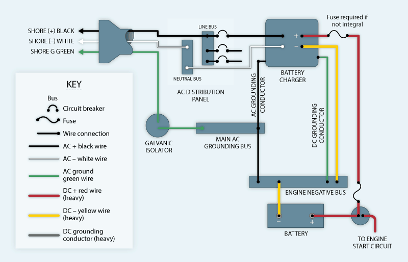
graphic by Stephen Rountree
Installation
AC CONNECTION—In boats with AC power distribution, the power will be supplied from the boat’s electrical panel. Your charger’s installation instructions will specify the appropriate wire diameter and the over-current protection. Before opening the electrical panel, be sure to disconnect the shore power cable or turn off the main AC inlet breaker which breaks both the hot and neutral wires. If the boat has an inverter, turn off the power supply to the inverter and confirm that any inverter circuits are dead before beginning the installation. Install a circuit breaker in the AC panel as stated by the charger manufacturer. Connect the charger input white wire to the breaker, the black wire to the AC ground buss at the back of the panel, and connect the green wire to the boat’s AC grounding bus.
Most runabout boats and center consoles do not have an AC electrical system. The battery charger will be the only AC device on the boat. For these simple applications, the AC connection might be as straightforward as plugging the battery charger cord into an extension cord, or, for this device installation, you may install an on-board charger inlet. This recessed three-prong 120-volt electrical plug is designed and permitted for this application. The battery charger may be directly wired into the built-in plug. To power the battery charger an extension cord is simply connected to this permanently installed plug. The power to this cord is supplied by a GFCI-protected outlet at the shore end.
DC Connection—Installing DC wiring gets more interesting. The size of the DC conductor is a function of the full length of the circuit, which includes the leg from the charger to the positive terminal plus the length of the DC negative lead back to the battery. This results in unusually hefty DC leads.
To comply with American Boat & Yacht (ABYC) marine standards, the DC+ wires must be fused at both ends. With marine chargers the device is often self-limiting—built so that it cannot produce more current than the DC wiring can handle. If not self-limiting, marine chargers will have either an integral breaker or a fuse on the output wire. You will not find this protection on most automotive chargers. What is frequently overlooked in marine installations is over-current protection (usually an inline fuse) at the battery (+) end of the wire. If the DC wire shorts out between the battery post and the charger, all the capacity of the battery can flow through the charger wire. This will overheat and melt the wire, potentially causing a fire. To prevent this, a fuse or breaker is required within seven inches of the battery connection.
Case ground—Another critical connection found in a marine charger is the heavy-case ground. In the diagram, you can see that the AC side of the charger has a case ground. So why do we need a DC case ground too? The AC case ground is sized to carry an AC case ground fault safely to shore. It is sized to carry the AC current, and that ground wire is protected by the AC overcurrent protection circuit breaker in the panel. Too much AC current on the green wire and the breaker will trip. However, a DC case fault will not trip the AC breaker. The DC current will flow through the AC case ground to the main AC grounding bus and from there to the engine negative bus and finally return to the battery from whence it came. This fault’s power is derived from the battery, so the AC breaker will not see that current. A DC fault will try to find ground through the AC green wire. The trouble is, the case ground is trying to conduct the full power of the stored energy in the battery through the small AC green wire. The green AC wire will release all its smoke and could start an onboard fire. The DC case ground must be able to carry the full DC current and it is required to be the same current capacity as the DC charger leads. This current is likely to be 10 times the current in the AC leads. For this reason, the DC case ground is required to be the same wire gauge as the battery charge
DC leads.
GALVANIC ISOLATION—If this battery charger installation is in a boat kept in a slip, this would be an excellent time to install a galvanic isolator. The galvanic isolator will continue to provide ground fault protection from an AC fault and will block any galvanic currents
from travelling in the shore power cord. An isolator will isolate your boat from all the other boats in the marina.
With a battery charger installed, your parasitic loads will be managed and the battery will be fully charged and ready to go when you are.
Electrical Wire Terminations
What the battery charger installation instructions don’t cover is how to correctly terminate wires. To correctly wire any electrical system in a boat you need two tools, a wire stripper and a ratchet crimper. Trimming the insulation with a knife will result in cut off strands. It’s important to use a proper stripper. Even more important is getting the crimp right. The small stamped-metal crimpers that are supplied with most wiring kits should be thrown out. I have had several of these over the years, and I’m pretty good with them. The last pair I threw out went nearly 80 feet. The only tool to use for marine wiring is a ratcheting-type crimper, which will not release until the crimp sleeve is fully compressed. With the standard non-ratchet tool you may not get full compression and the terminal end may be loose (high resistance) or may even fall off. After every crimp, give a firm pull on the wire terminal to be sure it is well crimped.
The wire terminals should be tinned ring terminals. Ring terminals will not fall off if the screw loosens. If the wires will be exposed to weather or salt air, heat shrink ends are perfect. Don’t ever use common household wire nuts in marine applications. They are designed for solid wire, not for stranded wire. They will cut and break strands inside the nut, and with vibration, they will come loose. An even worse wiring device is the insulation piercing clam-style connectors often used in trailer wiring kits. These connectors have very little electrical contact area. They may work (poorly) for the intermittent electrical loads in trailer lights but have no place carrying the larger loads in a battery charger installation. They are prone to heat buildup. Further, they pierce the insulation which will allow moisture into the wire resulting in corrosion.
Tom Hale grew up in a boat yard, designed and built boats up to 40 feet long, operated his own boatyard, and has been a technical advisor to the American Boat & Yacht Council (ABYC).